
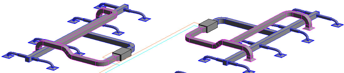
In the out-of-the-box Autodesk Revit mechanical template, the MEP (Mechanical, Electrical, and Plumbing) systems are assigned specific color values by default. For Mechanical duct systems, the Return Air is magenta, and the Supply Air is blue, as shown in the image below. System colors display in all views in the project, including 3D views.
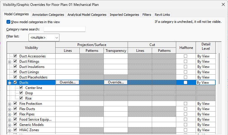
Sometimes, views become too cluttered, and colors are not as defined as you need them to be for your company standards. In such cases, you may need to hide certain systems in a view and change the color of the different systems. By default, the Visibility/Graphics Overrides dialog box only allows you to turn off categories such as Duct Accessories, Duct Fittings, and Ducts, as shown in the image below, but not specific duct systems.
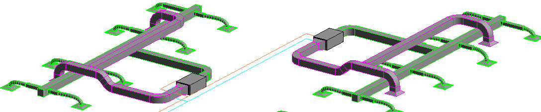
This is where Filters come into play. Any view can be set to display specific systems by using filters. Filters need to be set up per view and cannot be set up for all views in a project. In the example shown below, the view on the left displays all systems along with extra elements such as data components. The view on the right has graphic overrides and filters that toggle off extraneous elements and filter out all systems except duct and hydronic piping. You can also override the colors for the different systems in that specific view. 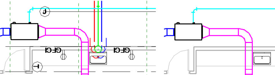
And finally, you can take it a step further and change the colors for the different systems for the entire project. In this blog, I will show you how to override duct systems; however, these procedures can also be applied to any electrical, piping, or plumbing system.
How To Apply a View Filter to Override MEP Systems in a Specific View
- Open the Visibility/Graphic Overrides dialog box by typing VV.
- In the dialog box, select the Filters tab.
- If needed, click Add to add Filters from the Add Filters dialog box. Additionally, you can also edit existing filters or create a new one as shown in the image below.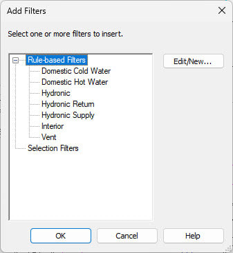
- In the Visibility column, check the overrides you want to display. In the image below, the Domestic and Sanitary categories have been toggled off, so they do not display in the 01 Mechanical Plan view, while the Mechanical systems are toggled on to display in this view.
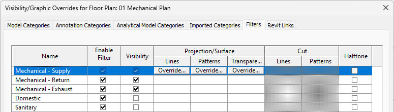
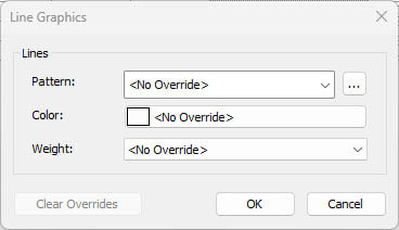
- In the Projection/Surface section>Lines column, you can click Override… and override the system Pattern, Color, and Weight in the specified view only. Remember, overrides set here will only affect the view specified at the top of the Visibility/Graphics Overrides dialog box.
How to Set Up Graphic Overrides on an MEP System for the Entire Project
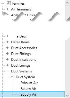
1. In the Project Browser, expand Families. Scroll down and expand Duct Systems>Duct System as shown in the image below. Double-click on the system you want to change. Alternatively, you can right-click and select Type Properties….
2. The Type Properties dialog box opens. Click Edit… next to Graphic Overrides.
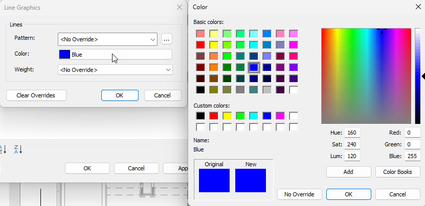
3. The Line Graphics dialog box opens and displays the current color for the Supply Air as shown in the image below.
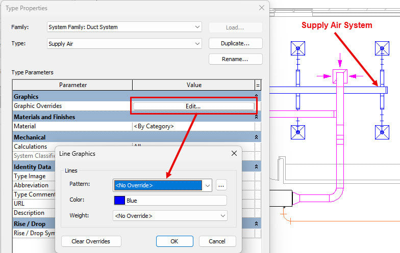
4. Click on the Color: value to open the Color dialog box as shown below. Select a new color for the Supply Air systems for the entire project and click OK.
5. Click OK in the Line Graphics and Type Properties dialog box to return to the model.
6. Open up several different views, like mechanical plan, section, elevation, and 3D view, as shown below, to see that the Supply ducts display with the newly selected color.
Customizing system graphics in Revit gives you more control over how your MEP models are displayed and communicated. Whether you need a quick filter to clean up a single view or a project-wide override to establish consistent system colors, these tools can make your drawings clearer and easier to understand. To learn more Revit MEP techniques, look at the Autodesk Revit 2026: Fundamentals for MEP learning guide.
About the Author
Follow on Linkedin More Content by Cherisse Biddulph


