
The AutoCAD Electrical software supports the use of multiple drawings using project files, which are managed through the Project Manager palette. Understanding the Project Manager palette enables you to efficiently navigate the project files and work with multiple drawings in projects to successfully create electrical designs.
Project Files
Typically, an electrical design requires many drawings. The AutoCAD Electrical software supports the use of multiple drawings using project files.
-
A project file is a text file that contains a list of drawings that are part of a specific design. Project files contain settings for the project and are created and maintained using the Project Manager palette.
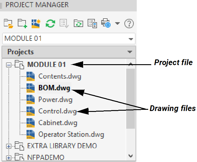
- There is no limit to the number of drawings that a project file can contain.
-
Project files have a .WDP file extension.
-
You can have multiple projects open, but only one is active at a time. The active project is the set of drawings that are processed using AutoCAD Electrical commands.
Project Manager
The Project Manager is a palette interface used to create and manage AutoCAD Electrical project files. It has the same functionality as any other AutoCAD Tool Palette and contains options for docking, anchoring, and auto-hiding.
The Project Manager palette contains the Projects tab and the Location View tab along the right side of the palette. The display of the Project Manager interface depends on the tab you have selected.
Project Tab
The Projects tab is selected by default in the Project Manager. It has the following areas:

-
Toolbar
The Project Manager contains a toolbar across the top. It enables you to open an existing project, create a new project or drawing, make project-wide updates, access the print commands, access the AutoCAD Electrical Help system, etc.

-
Drop-down List
A drop-down list is available just below the toolbar. You can use it to activate a project, open an existing project, or create a new project.

-
Projects Area
The Projects area displays the open projects in the form of a list. When expanded, it displays the drawings and subfolders that are part of each project in a tree structure. Shortcut menu options are available by right-clicking on project files and drawing files in the Projects area.

-
A project can be organized into subfolders that group related drawings.

-
The Projects area contains specific shortcut menus for DWG files, project files, and subfolders.
-
The Projects area can be customized to display a combination of a DWG filename and its AutoCAD Electrical specific properties (Description).

-
Details/Preview Area
The Details/Preview area is located below the Projects area. The area displays information about the selected project file or drawing, including its name, location, and AutoCAD Electrical properties. You can either display a preview of a drawing file or display the details of the drawing file.

Location View Tab
When the Location View tab is selected, the interface of the Project Manager palette displays information about the connections and components in the projects. All the devices that are present in the project are listed along with their location in a tree structure.

-
Hovering the cursor over a component in the list displays its information.

-
In the Project Manager toolbar (Location View tab), click
 (Display Details and Connections) to expand the view and display the details and connections information of the selected node or device.
-
The Details tab displays the details of the selected node/device.

-
The Connections tab displays the wiring and from/to connections of the selected node/device.

Accessing project files in the Project Manager (Projects tab) is the first step when creating a new set of electrical drawings or accessing an existing set. I hope you found the information provided here helpful! In addition to this explanation, a hands-on practice about how to use the Project Manager is provided in our AutoCAD Electrical Fundamentals with NFPA Standards learning guide.
About the Author
Follow on Linkedin More Content by Renu Muthoo


