
As I mentioned at the end of my previous blog Sheet Metal Face Features in 2025, the interface for Sheet Metal Cut features has also been updated with the release of Inventor 2025. For those new to using the Properties panel for any Cut feature, I have included an overview. For those already familiar, there are really no significant differences in the functionality. The biggest impact will be where to find the options.
Use the following general steps to create a Cut feature:
1. Create a closed loop sketch to use as the profile for the cut.
2. In the Sheet Metal tab>Modify panel, click  (Cut). The Properties panel opens.
3. Select the profile and define its options. If a single closed section sketch exists, it will be automatically selected. If not, the Profiles field should be active (blue underline), and you can select the profile. If the profile needs to be wrapped around a bend, you can use either of the following settings:
- Enable the  (Cut Across Bend) option to wrap the profile around a radius to the next face and cut through that face, as shown below. This type of cut would be made on an actual part, while the sheet metal is still flat before bending.

- Disable the  (Cut Across Bend) option to extrude the feature normal to the sketch plane, as shown below. The resulting shape only matches the profile as far as the depth of the Cut feature (dependent on the Extent option that is used).

- To customize how a cut is extruded through sheet metal geometry over bent geometry, you can use the  (Cut Normal) option. When this option is disabled, the cut is created normal to the sketch plane through the geometry. If enabled
  (blue highlight on the command), the cut is created normal to the face of the geometry, NOT the sketch plane, as shown below.

4. Once you assign the profile, you can define the Distance (depth) of the cut using the options in the Behavior area. The options that are available will depend on whether you are cutting across the bend or not.
-
- If the (Cut Across Bend) option is enabled, the cut is, by default, cut to the sheet metal Thickness parameter.
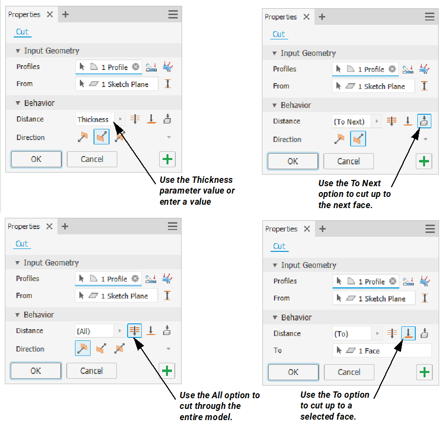
- If the (Cut Across Bend) option is disabled, you can control the distance of the cut as shown below.
- If the
5. Use the Direction option to flip the cut in either direction ( ,
, ) or symmetrically on both sides of the sketch plane (
 ). Note that the Direction options are only available when the Cut Across Bend option is disabled.
6. Click OK to complete the cut feature.
I hope that you enjoy this new and subtle change to the Cut feature in the interface.
About the Author
Follow on Linkedin More Content by Jennifer MacMillan


