
In a previous blog post, I had discussed Pipe styles in Civil 3D. This blog complements that post by addressing Structure styles in Civil 3D.
Structure Display
Similar to pipe styles, the structure style defines how a Structure is presented in model, plan, profile, and section views. The display options for the structure vary based on the view, as described below:
- For the model view, the structure can be viewed as a catalog defined part or a simple 3D part.
- For the plan view, the structure can be viewed as the simple outer part boundary or as a block that is defined in the drawing. If using a block, you have to determine the scale and sizing options for the block.
- For the profile view, the options are the same as those for the plan view, in addition to displaying the structure as a solid.
For the section view, the options are the same as those for the profile view, in addition to displaying the structure as a slice of the structure. 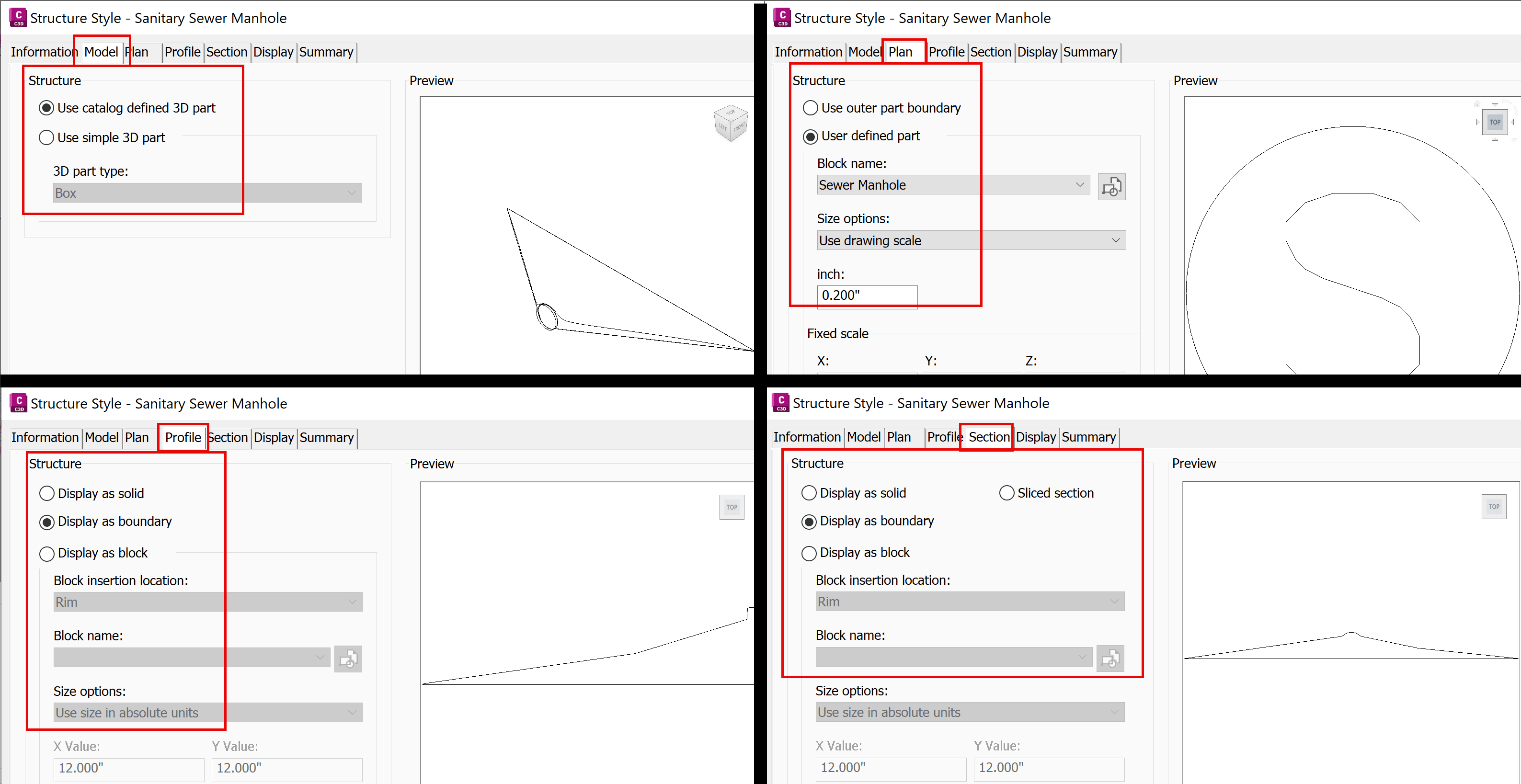
Symbols for structures usually conform to drafting and mapping standards. However, it's sometimes useful to see the physical outline of a structure. Let us further examine this topic.
The Structure Style dialog box
The Structure Style dialog box has multiple tabs:
- Information
- Plan
- Profile
- Section
- Display
- Summary
The Information tab provides a proper name and description for the style, as well as the name of its creator and who had modified it last.
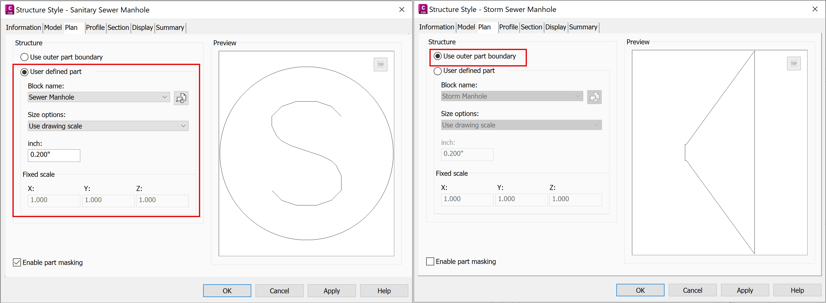
The Plan tab controls how each structure component is displayed. The default option is User defined part, as shown on the left. Select Use outer part boundary instead to view the actual outline and size of the structure (such as a manhole).
Select the Profile tab and then the Section tab and note that both are already set to - Display as boundary.
See the results in the following figure. On the left is the customary symbol for a manhole, on the right the actual shape and size of the structure. 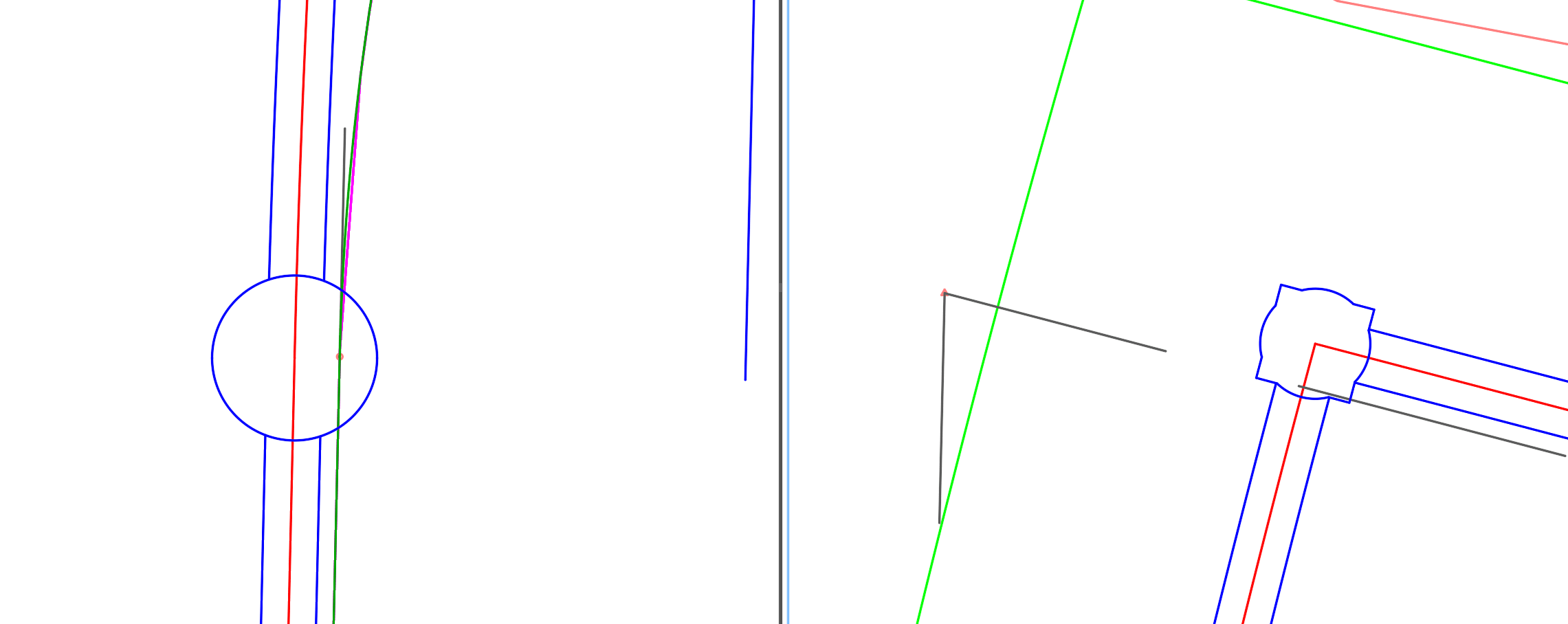
Conclusion
Structure and Pipe styles in Civil 3D are versatile. With proper management of such styles, you can make Civil 3D drawings emulate various drafting practices for plan views, profiles, or section views. The example used in this blog post demonstrated how to view the actual shape and size of a structure like a manhole in plan view.
About the Author
Follow on Linkedin More Content by Jeff Morris


